2-Chloropropionyl chloride → 4-Chloro-1-phenylpentan-3-one
Reaktionsgleichung

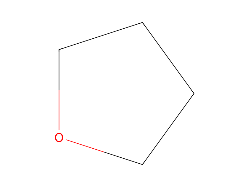
[Cl:1][CH:2]([CH3:6])[C:3](Cl)=[O:4].[CH2:7]([Mg]Br)[CH2:8][C:9]1[CH:14]=[CH:13][CH:12]=[CH:11][CH:10]=1>O1CCCC1>[Cl:1][CH:2]([CH3:6])[C:3](=[O:4])[CH2:7][CH2:8][C:9]1[CH:14]=[CH:13][CH:12]=[CH:11][CH:10]=1Komponenten
4
Edukt 2


Produkt 1

Reagenzien, Katalysatoren, Lösungsmittel 1
Versuchsvorschrift
In two multi-injection microreactors having 4 reaction regions (each comprising one injection point, one mixing zone and one reaction zone of 1.08 mL internal reaction volume), 2-chloro propionic chloride (13.5 wt %) in tetrahydrofuran (THF, 86.5 wt %) as flow A and phenethyl-magnesium bromide (1 eq., 10 wt %) in THF (1 eq., 90 wt %) as flow B were reacted. Micro-reactor MR1 comprised internal heat exchange structures and provided a very efficient cooling (VEC) while temperature adjustment of metal microreactor MR2 was performed by submersing the microreactor in a temperature adjusted bath and provided only a low efficient cooling (LEC) between the injection points. The temperatures were displayed in table 3. Total flow rates of 20 and 40 g/min after last injection were performed. The 2nd reactant (flow B) is fed to the first reactant in a proportion corresponding to the number of inlet points. About 25 mol-% of flow B necessary to reach completion of the reaction respectively were fed at each inlet point to the first flow. After the last injection the reagents of flow B and flow A were fed in equimolar amount. The yields of the product 4-chloro-1-phenyl-pentan-3-one being collected after the respective reaction zone and quenched are shown in table 2 in relation to feed rate and cooling conditions.